

Arvid Schneider is an awesome guy that creates extremely high quality tutorials. Check out his website and Youtube Channel. He made a great tutorial on how to create Captain America’s shield, teaching a thing or two about anisotropy. https://www.youtube.com/watch?v=qKpynSqvAVc He covers a lot of topics in a very short time. I had some difficulties to follow a couple of his steps. So here is a rewrite of the tutorial with my personal preferred way of doing things. However definatly go check out the video, he describes the steps in much greater detail. # Part 1: Modeling the shield I am going to be using a Poly Sphere to create the shield.
Step 1
Create a **Poly Sphere**. In faces mode select the lower part of the ball. 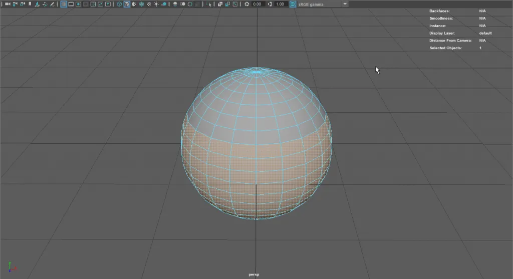
Step 2
(If you selected a little more than the half re-position the Pivot Point) Scale the half-sphere down. 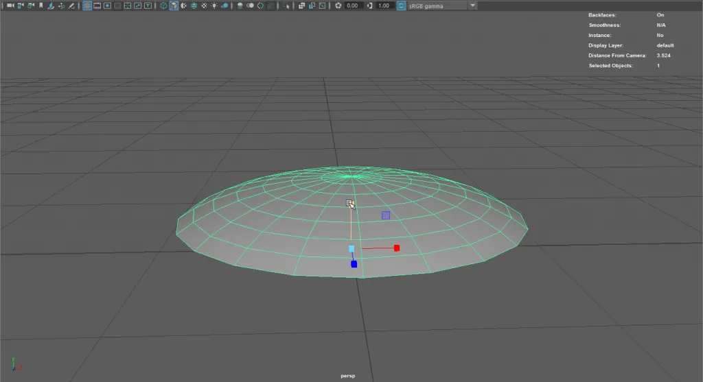
Step 3
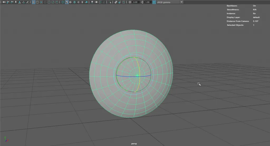
RotateZ = 90
Step 4
Create a UV-Layout. The important thing is, since in the tutorial a lot of ramps with the circular attribute are going to be used that the center of the UVs are placed exactly in the middle. The easiest way to get a perfect placement is to use “UV > Planar”, and Project from the X-Axis. 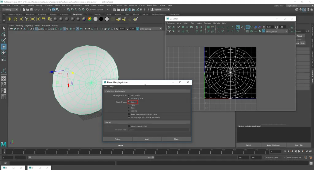
Part 2: Initial Render Setup
Step 1: Camera
- Create a Render_Cam (**Create > Camera > Camera**)
- **Panels > Look through Selected**
- **View > Camera Settings > Resolution Gate**
- Position the Camera
Initially I set up the camera just like in the tutorial with the shield slightly slanted. This setup has the benefit that you can clearly see the reflections. For the final image I chose to re-position the camera for a more frontal view of the shield. 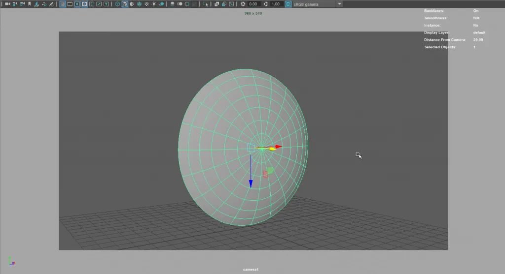
Step 2: Lighting
Arvid Schneider does not go into his lighting Setup, in essence he has a “Studio Lighting” and a “Outdoor Lighting” HDR setup. I only used a basic Studio Lighting with the help of two Area Lights, (Exposure 12, and Exposure 17) 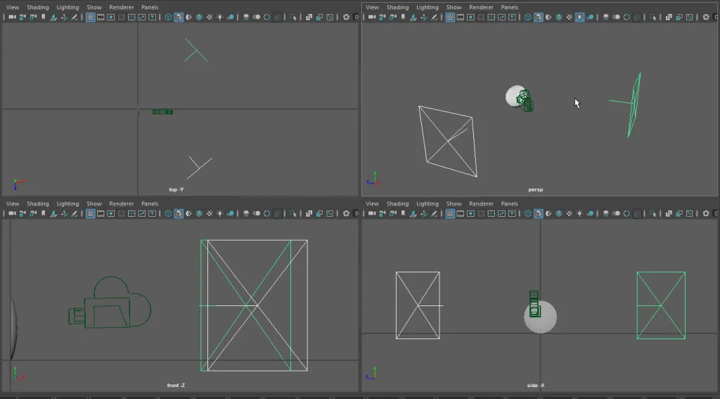 # Part 3: The Shader Arvid Schneider recommends to connect the newly created ramp into the diffuse color attribute, so you can immediately see the color output
Step 1: alShader
Create a new alShader “al_shield” and assign it to the shield.
Step 2: Base Colors + Star
In the Hypershade editor press _Tab_ and create a new “ramp (texture)” (base_color), connect it directly to the diffuse color of the alShader. Change the Type to “Circular Ramp” and the Interpolation to “None” In the Attribute Editor adjust the colors of the gradient: 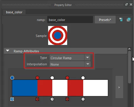
Use a reference image of the shield, and the Arnold Renderview to determine how wide the various segments of the gradient need to be.
To add the star, first google for a star image. (The star should be white, if not you should edit it in Photoshop) In the Hypershade create a “aiCombineColor” Node, Change the Combine Op to *add 1+2*.
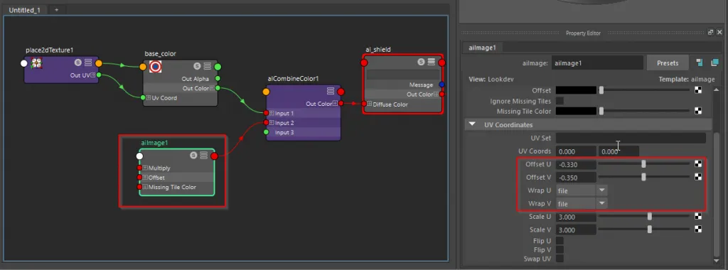
Connect the ramp “base_color” to input1 and “out color” to “al_shield” Diffuse Color. 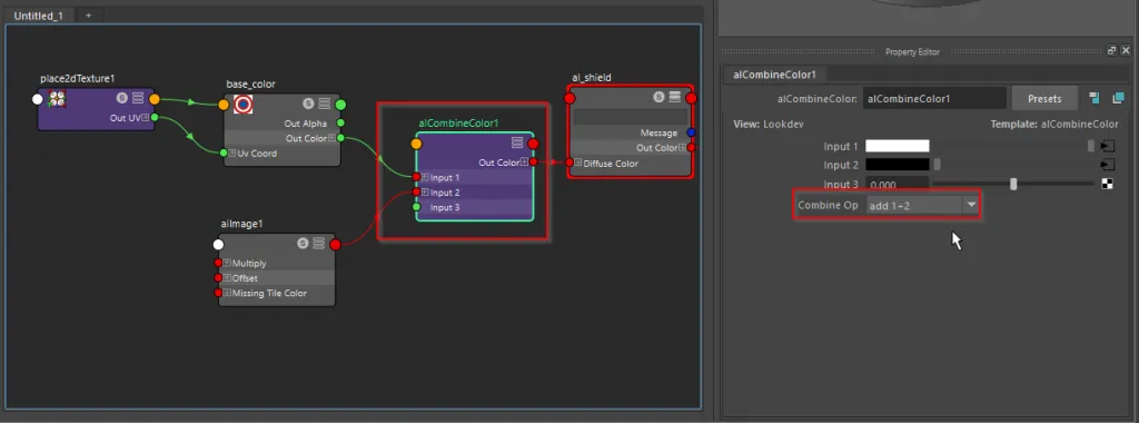 Create an aiImage Node, import the star and connect it to input 2. Change **Wrap U** and **Wrap V** to **file**, to ensure that you only have a single star.
With **Scale U** and **Scale V**, you can make the star bigger or smaller (larger numbers make the star smaller, smaller numbers makes the star bigger) Finally position the star using the **Offset U** and **Offset V** Attributes.
Create an aiImage Node, import the star and connect it to input 2. Change **Wrap U** and **Wrap V** to **file**, to ensure that you only have a single star.
With **Scale U** and **Scale V**, you can make the star bigger or smaller (larger numbers make the star smaller, smaller numbers makes the star bigger) Finally position the star using the **Offset U** and **Offset V** Attributes.
 If everything is looking good, break the connection to the “diffuse color” and connect the aiCombineColor1 to the **Specular 2 Edge Tint** and to the **Specular Color 2 Reflectivity**.
Set the Strength of Reflectivity 2 to 1 and the Fresnel Mode to metallic.
If everything is looking good, break the connection to the “diffuse color” and connect the aiCombineColor1 to the **Specular 2 Edge Tint** and to the **Specular Color 2 Reflectivity**.
Set the Strength of Reflectivity 2 to 1 and the Fresnel Mode to metallic. 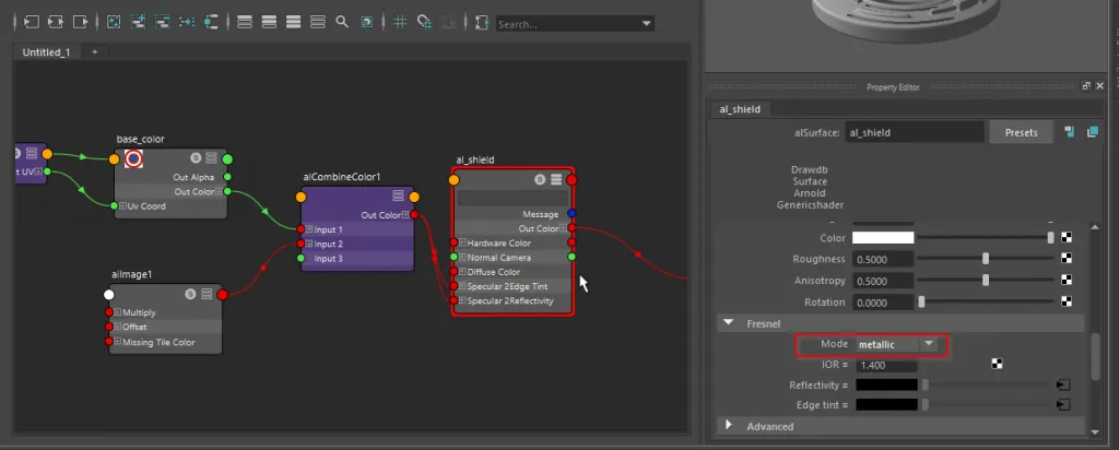 [caption id=“attachment_660” align=“aligncenter” width=“960”]
 Step 2 Complete[/caption]
Step 3: Ansiotropic Map
The Ansiotropic Map is going to be used as a bumpmap, and should simulate the small ridges in the surface. In the Hypershade create a “ramp (Texture)”, name it ramp1. (Make it Type Circular) Open the Script Editor (python) and use following code to create a ramp with many many small ridges.
import pymel.core as pm
import random

ramp = pm.PyNode("ramp1")
count = 2500

for i in range(count):
position = i/float(count)
colorR = random.uniform(0,0.05)
ramp.colorEntryList\[i\].position.set(position)
ramp.colorEntryList\[i\].color.set((colorR,colorR,colorR))
Additionally you could play around with the noise attributes of the ramp to create a more realistic look. 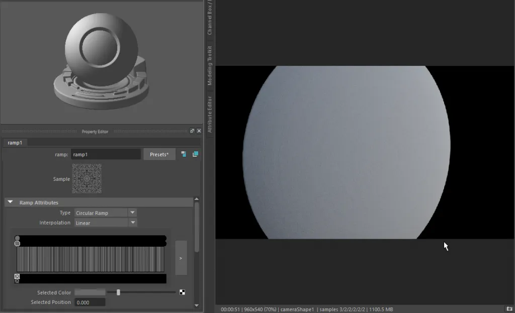 You can further enhance the difference between the different colors of the shield by combining this ramp with another ramp using an aiCombineColor Node. Go to the “base_color” ramp, and save it as a preset, then create a new ramp with interpolation “Spike” and load the colors from the preset. Then change all colors to black, and add white points left and right so you get a ramp looking like this:
 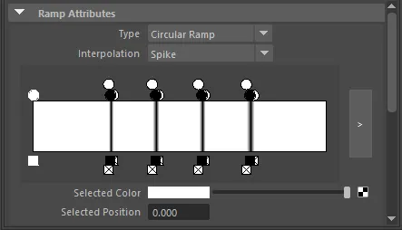 Save your scene, while connecting the Map to the Bump Mapping Attribute, my system crashed a lot. Finally create a “bump2D” Node, as Input use “Out Color R” and connect it to the “ai_shield” bump.
 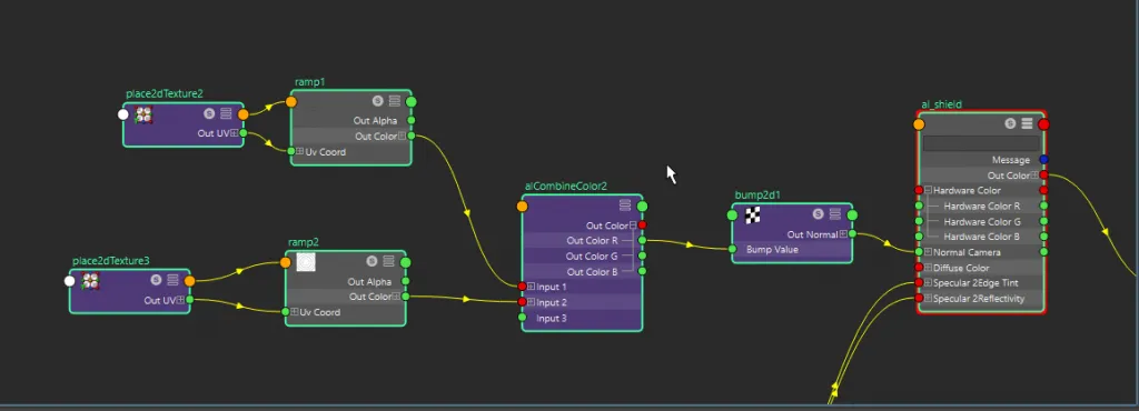 [caption id=“attachment_665” align=“aligncenter” width=“960”]
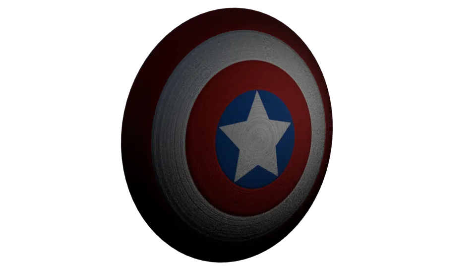 Step 3: Complete[/caption]
Step 5: Specular 1 Ansiotropy Values
Create another ramp (texture) and create a gradient like this: 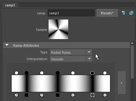 This texture drives the Specular 1 Ansiotropy Values. Simply connect it to the Attribute.
Step 6: Final Settings “ai_shield”
Base settings:
- Diffuse Color Strength = 0
- Specular 1 Strength = 0.25
- Specular 2 Strength = 1
You should play around with the Roughness settings of Specular 1 and 2 to adjust the Reducing Specular 2 Roughness, makes the shield shinier.
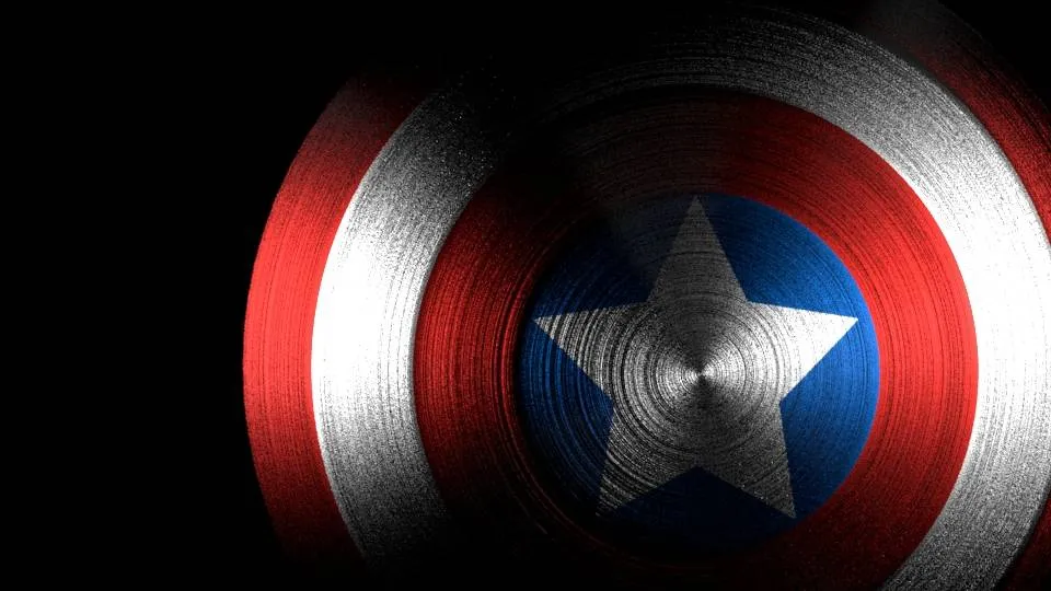 Playing around with Roughness values
Finally Arvid Schneider uses a noise map to drive the Specular 2 Strength setting, which would make the shield look dirty.

About Neal Burger
Neal Burger is a successful entrepreuner. He is the founder of Acme Inc, a bootstrapped business that builds affordable SaaS tools for local news, indie publishers, and other small businesses.